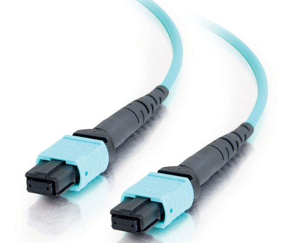
MPO connector by consist of Dust Cap、Outer housing、MT Ferrule、Pin、Spring、Spring Push、Crimp Ring、Boot. MPO connectors utilize precision molded MT ferrules, with metal guide pins and precise housing dimensions to ensure fiber alignment when mating. The MPO can be mass terminated in combinations of 4, 8, or 12 fiber ribbon cables.

MPO connections used in high-density backplane and Printed Circuit Board (PCB) applicationsin data and telecommunications systems. The MPO connector offers up to 12 times the density of standard connectors, providing significant space and cost savings.The MPO’s rise in popularity stems from its unique ability to mate multiple fibers (2-72 fibers) within a single connector body housing therefore significantly reducing space.
The connector’s general design also has unique features from conventional connectors such as being rectangular in shape. It utilizes guide pins and precision holes for ferrule to ferrule alignment within the adaptor as opposed to a precision alignment “sleeve” used in conventional connector and the ferrule (MT) is made from a monolithic, high precision glassed filled polymer as opposed to a ceramic material. MPO Plus Series of enhanced MPO style  connectors has taken a leadership role in refining and optimizing the original product in the areas of mechanical durability, product features and most importantly the optical performance of the MT ferrule itself.
The TIA 568 standard provides three methods for configuring systems to ensure that proper connections are made. These three methods differ in the cable orientation, connector orientation and the fiber assignment.
which is either “Key Up to Key Down” or “Key Up to Key Up”. In addition, MPO connectors are differentiated to a Male and Female connector. A Male MPO connector has two alignment pins while a Female MPO connector has two alignment holes where the pins are to be inserted when a termination is performed. An MPO connection can only be performed between a Male and Female connector to ensure proper alignment which is required to maintain a low loss connection.
Method A:has fiber 1 in position 1 in the MPO connector at both ends of the patch cord and is maintained throughout the network.

Method B:one end of the connector fiber 1 is located at position 12 while fiber 12 is located at position 1.
Method C: Fiber 1 in position 2 while fiber 2 in position 1. This repeats throughout the whole connector.
The fiber optic cable is a network cable that contains strands of glass fibers inside an insulated casing. They’re designed for long distance, very high performance data networking, and telecommunications. Fiber optic cables support much of the world’s internet, cable television, and telephone systems.


