In any installation, it is important to ensure that the optical transmitter at one end is connected to the optical receiver at the other. This matching of the transmit signal (Tx) to the receive equipment (Rx) at both ends of the fiber optic cable is referred to as polarity.
Generally, an optical cable needs two optical fibers to complete the whole transmission process. For example, the optical module includes the receiving end and the transmitting end. When used, it must ensure that the receiving end and the transmitting end are in an interconnected state. The matching between the sending end (TX) and the receiving end (Rx) at both ends of the optical cable is called polarity.
There are three polarity methods specified in the standard, namely, Type A (key up to key down) Type B (key up to key up), and Type C (key up to key down paired staggered Type).
Type A: MTP/MPO number of cores at both ends in parallel arrangement,
1 corresponding to 1
2 corresponding to 2
3 corresponding to 3…
Type B: MTP/MPO cores at both ends are completely crossed,Key UP corresponds to Key UP:
1 corresponding to 12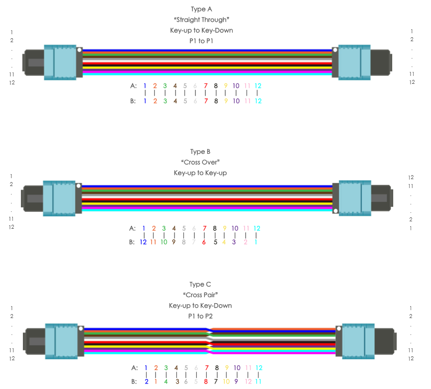
2 corresponding to 11
12 corresponding to 1
11 corresponding to 2…
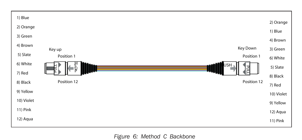
Type C (pair-wise staggered): MTP/MPO number of two cores crossed in pairs, and Key orientation corresponds to Key UP corresponds to Key Down:
1 corresponding to 2
2 corresponding to 1
11 corresponding to 12
12 corresponding 11…
MPO connector
An MPO connector can support 12 -, 24 -, 36 -, and 72-core fiber optic connections. Each MPO connector has a key way that is called Key up when the key way is in the upper half of the connector and Key down when the key way is in the lower half. There is a point on one side of the MPO connector to mark the position of the first core hole.
MPO adapter
The MPO connector (male head) and the MPO connector (female head) are paired through the MPO adapter. There are two types of MPO adapters, type A and type B: type A the keyway on one side of the adapter is up, and the keyway on the other side is down. Therefore, when connecting two MPO connectors, the key slots for both connectors are on parallel lines. Type B the inner keyways on both sides of the B adapter face up, so when connecting two MPO connectors, the keyways of the two connectors are in a straight line.
MPO cable
Both ends of the MPO backbone cable are pre-terminated with (male/female) MPO connector, which can support 12 core, 24 core, 48 core and 72 core fiber connection. MPO branch cable: one end of the MPO branch cable is pre-terminated with a (male/female) MPO connector, and the other end is pre-terminated with multiple duplex LC/SC connectors, supporting the conversion of multi-core cable to single-core or dual-core cable. MPO transfer module box: the MPO transfer module box adopts closed box structure, which can contain 12 or 24 cores of pre-terminated MPO branch cable. The figure below shows 2 MPO connectors and 12 MPO transfer module boxes of duplex LC interfaces.
How to manage polarity
This section describes how to ensure the correct polarity of the connection of MPO optical devices under the TIA standard. The three polarity methods specified in TIA568 are called type A, type B, and type C.
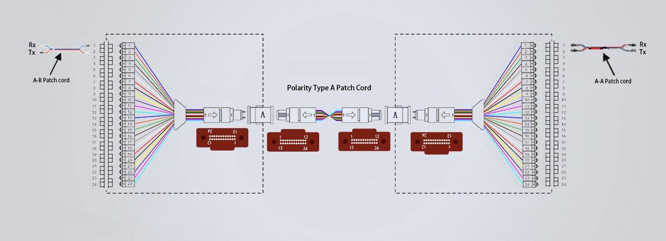
Type A: One end of the patch is a straight through pair and the other end is an inverted pair. (Rx for receiving, Tx for transmitting) which USES the direct MPO backbone cable to ensure the accuracy of polarity.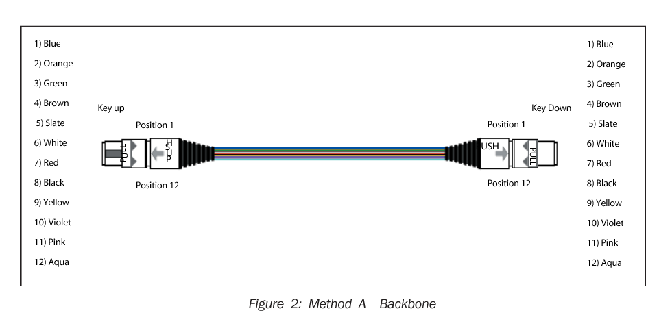
Type B: The utility model adopts a straight through wiring module and a straight through wire pair patch. The figure below shows the type B connection. This connection USES the fully crossed MPO backbone cable, and because the fibers at each end of the fully crossed MPO backbone are in opposite positions, the standard a-b patch is used at both ends of the fiber chain.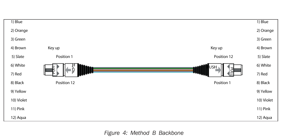
Type C: The main cable is used in the reversal of the line pair to correct the polarity, the use of the same module and the same patch.The figure below shows the C type connection. Type C connections are wire-to-wire intersecting MPO backbone cables, and standard a-b patchs are used at both ends of the fiber optic cable.